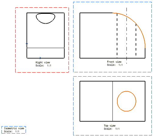
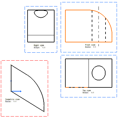
- You will first add elements to an existing view, using the Action-Object mode.
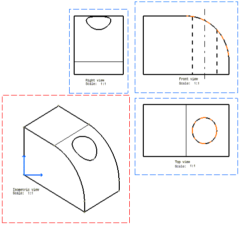
- You will then create an isometric view from scratch, using the Object-Action mode.
Activate the view you want to create the new geometry in.
Add elements to an existing view, using the Action-Object mode
OR

3. Select, in another view, the object to be projected. In this case, select a circle in the top view.
4. Select more elements to be projected, if needed, or click in the open space or still another command if you want to terminate this command.

Create an isometric view from scratch, using the Object-Action mode
1. Make the isometric view active (double-click).
2. Multi-select the elements to be projected into the isometric empty view. In this case, select the whole front view.
3. Click the Multiple View
Projection icon
![]() from the Multi View toolbar.
from the Multi View toolbar.
4. Select the object defining the view to be created.
All the elements are automatically projected onto the active view.

5. Repeat the steps above (Object-Action) with the various elements to be projected that will allow generating the isometric view.

![]()