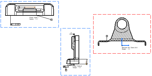
A view from 3D is extracted from a 3D part, product or process that is assigned 3D tolerance specifications and annotations. The master document is the 3D part, product or process, which means that everything is handled at the 3D level: view definition (projection view, section view, section cut), annotation content and graphism. For this reason, it is recommended to perform modifications directly in 3D.
You can generate the following types of view from 3D:
Creating projection views, section views, section cuts |
|
Go to Tools > Options > Mechanical Design > Drafting > View tab and make sure that Exact preview for view generation is selected as the view generation mode in the View Generation area (other view generation modes - CGR, Approximate and Raster - are not supported).
-
Click View From 3D
 in the Views toolbar (Projections sub-toolbar).
 -
Select a view from the 3D, either in the specification tree or on the part. In this case, select Front View.1 in the specification tree.
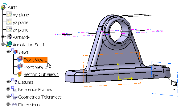
The view to be created is previewed (included annotations) on the sheet. You cannot modify the view orientation, but you can modify the view position by dragging it using the left mouse button.
-
Click on the sheet to create the new view.
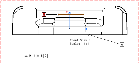
You can notice that one of the extracted annotations (datum B) bears a red cross mark, which indicates that the leader cannot be extracted linked to the geometry. This is because the 3D annotation leader is linked to 3D geometry, which is not visible in the 2D view (i.e. hidden geometry).

Such a red cross mark will be used for any annotation or dimension with a leader linked to hidden geometry (i.e. 3D geometry which is not visible in a 2D view). You can either change the properties of the view from 3D (Edit > Properties) to display hidden lines, or transfer the marked annotations to a 3D view where the associated geometry will be visible when extracted. -
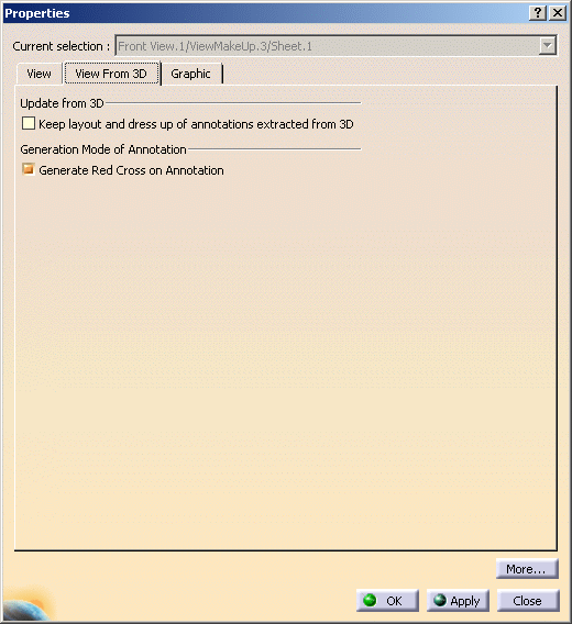
To visualize the annotations marked with red cross, right-click the view and select Properties, or go to Edit > Properties. The Properties dialog box is displayed.
-
Select the View From 3D tab, Generation Mode of Annotation area and clear the Generate Red Cross on Annotation check box (by default, this check box is selected).
-
Click OK.
All the annotations in the view are updated. The view is updated as shown.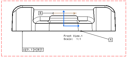
The properties of views present can be individually updated. The state of the Generate Red Cross on Annotation option is saved with the view.

To create the newly generated views without the red cross mark, go to Tools > Options > Mechanical Design > Drafting, View tab, View from 3D area, clear the Generate red cross on annotation check box. All the newly created views from 3D do not have the red cross mark. -
Repeat the first three steps, this time selecting Front View.2 as the view to be created.
-
Once again, repeat the first two steps, this time selecting Section Cut View.1. The preview is displayed on the sheet.
-
On the sheet, click Front View.2 to specify that the callout for the section cut should be positioned in that view. Note that it works the same for section views.
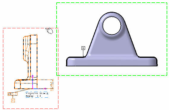
In views from 3D, the axis can only be that of the sheet: the H and V axis of the view must correspond to X and Y axis of the sheet.
For this reason, the choice of the view in which to add a section cut callout is limited.
In particular, the profile of the section cut must be horizontal on the chosen view.
In the case of extraction views, the first line of the profile (i.e. corresponding to the first compounding view) must be horizontal.
Creating aligned section views/section cuts and offset section views/section cuts |
|
Go to Tools > Options > Mechanical Design > Drafting > View tab and make sure that Exact view is selected as the view generation mode in the View Generation area (other view generation modes - CGR, Approximate and Raster - are not supported).
-
Click View From 3D
 in the Views toolbar (Projections sub-toolbar).
 -
Select the aligned section view from the 3D, either in the specification tree or on the part. In this case, select Aligned Section View.1 in the specification tree.
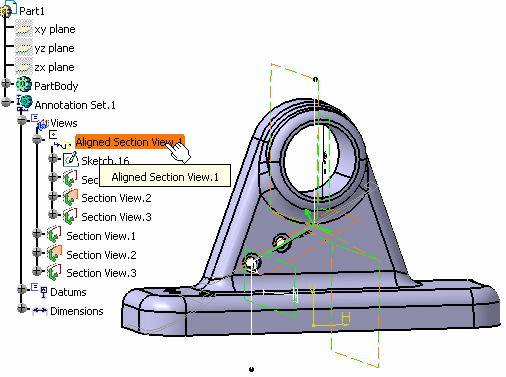
The view to be created is previewed (included annotations) on the sheet. You cannot modify the view orientation, but you can modify the view position by dragging it using the right mouse button.
-
Click on the sheet to create the new view.
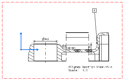
More About Views from 3D
- Only the elements visualized in the 3D (i.e. in Show mode) at the time of extraction are extracted in the view from 3D. In other words, any element hidden in the 3D will not appear in the view. If you then show this element in the 3D part, it will be displayed in the view from 3D after you update it.
- You can move or modify annotations in views from 3D. However, if the part is modified and you subsequently update the view, any modification applied to the annotations in the drawing will be lost. We advise you perform modifications on the 3D part directly.
- Extracted annotations are not associative to the geometry.
- How you can know what geometrical elements an annotation is applied
to depends on what workbench you are in. In Functional Tolerancing and
Annotation, the 3D Annotation Query Switch On/Switch Off tool
highlights such geometrical elements. In Drafting, leaders are attached to
these geometrical elements.
As a consequence of this behavior, when a 3D annotation is extracted in a drawing, the annotation position may change from the position defined in 3D (because the leader may be moved in order to point to the extracted geometry):- when a leader is not associative in the 3D and does not point to the 3D geometry.
- when the extracted geometry pointed by the leader is hidden in the drawing by other extracted geometries.
- 2D annotations can be added to views from 3D.
- In views from 3D, the horizontal axis of the view is parallel to the horizontal axis of the sheet.
- You can create views from 3D from a part (Functional Tolerancing and Annotation workbench), a product (Product Functional Tolerancing and Annotation workbench) or a process (Process Tolerancing and Annotation workbench). It is currently impossible to extract views from part, product and process at once. However, you can superpose views as a bypass (using the View Positioning > Superpose contextual command).
- Views from 3D are not associative to the geometry of the 3D view. So, if you modify the geometry of a 3D view, the definition of the corresponding 2D view will not be modified at the next update, even if the 3D view is associative to the geometry.
- The Note Object Attribute (NOA) from a ditto (2D component) is now
extracted in views from 3D. However, some restrictions apply:
- If a frame is defined in 3D, this frame is not displayed in the 2D view. To work around this, do not use the 3D annotation frame when defining the NOA reference; instead, have your administrator define the frame as part of the 2D component geometry.
- Information regarding the documents used to create the ditto (drawing, parts, catalogs) will be lost.
- Hidden texts and URLs on flag notes and Note Object Attributes will be lost during extraction.
- Views from 3D can be rotated. In other words, when you edit the properties of this view (Edit > Properties), the Angle field can be edited and customized according to your needs.
- When editing the properties of a view from 3D (Edit > Properties),
a specific tab is available: View from 3D. In this tab, you
can select the Keep layout and dress-up of 2D extracted annotations
check box to preserve the layout and dress-up applied to 2D extracted
annotations when updating a view from 3D. In this case:
- 2D dress-up modifications are kept when updating design changes from 3D.
- Associativity of the annotations or their leader with the 3D geometry is taken into account.
- Associativity between annotations is taken into account.
Ratio of an Annotation Generated From FTA
- For front views, section views and section cuts, the ratio of the 3D annotation view is reversed and applied in the generated 2D drafting view.
- For aligned section views/section cuts and offset section views/section cuts, the ratio of the first 3D annotation view is reversed and applied to all the generated 2D drafting views.
![]()
