Modifying the Existing Callout Geometry |
|
-
Double-click the callout to be modified. The Edit/Replace toolbar appears.

-
Drag one of the element components to the desired location. In this particular case, drag one segment extremity of the callout.
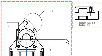

-
By default the segment extremities are not fixed.
-
To constrain one segment, right-click this segment and select Line.object > Fix.
-
To free one segment, right-click this segment and select Line.object > Unfix.
-
-
Click End Profile Edition
 in the Edit/Replace toolbar.
The callout arrow is now properly positioned and the section view (B-B) is automatically updated.
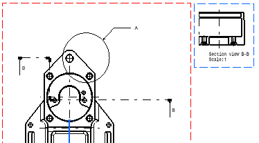
Reversing the Callout Direction |
|
-
Double-click the callout to be reversed.
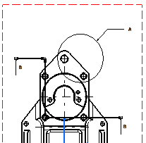
The Edit/Replace toolbar appears.
-
Click Invert Profile Direction
 in this
toolbar.
in this
toolbar.The callout is automatically inverted.
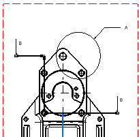
- At any time, you can stop editing the callout by clicking End Profile Edition in the Edit/Replace toolbar.
- You cannot reverse the callout of a detail.
- If the modification of a view containing a callout makes the projection planes of the defining and the resulting views inconsistent, the callout turns red indicating that there is an inconsistency in the drawing. For more information, refer to More about red callouts below.
Replacing the Callout |
|
-
Double-click the callout to be replaced.
The Edit/Replace toolbar appears.
-
Click Replace Profile
 in this toolbar.
 -
Create the new profile.
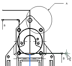
-
Double-click to end the new profile creation.
The new profile automatically appears and the old one disappears.
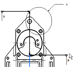
Recreating the Callout |
|
Callouts can be recreated in any of the following conditions:
-
Callout has been manually deleted.
-
View containing the callout has been deleted.
-
View has been cut/pasted in another drawing.
-
View containing the callout has been modified and the callout has became invalid (red callout).
The following types of callouts can be recreated:
-
section callouts
-
detail callouts
-
projection callouts.
The recreated callout type (section, detail or projection) is given by the resulting view definition and is not defined or specified by you.
| If the resulting view is... | and projection planes of resulting and new defining views are... | the recreated callout is... | |
|---|---|---|---|
| an Auxiliary view |
|
perpendicular | a projection callout |
| a Section view |
|
perpendicular | a section callout |
| a Detail view |
|
parallel | a detail callout |
| a Detailed section view (*) |
|
parallel | a detail callout |
* In this case the defining and resulting view section
profiles have to be equal.
To recreate a callout:
-
In this case you can see that the callout for Detail A, has been deleted. Activate the detail view and follow the procedure given.
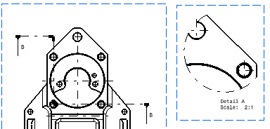
Right-click the view and select Detail X object > Add Callout.
This command is also available through the menu command Edit > Detail X object > Add Callout.
- If the resulting view already has a valid
callout in the defining view then the following error message
is displayed:

- If the resulting view has a invalid
callout (red in display) then the following warning message is
displayed, but the command continues to the next step:
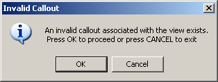
-
Click on the main defining view where you want to recreate the callout. The callout is recreated and the red invalid callout is removed in case it is present.
In this case you can see that callout for Detail A is recreated.
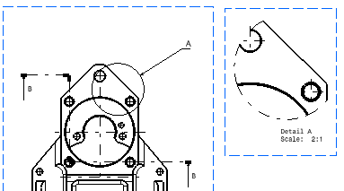
To recreate the callout, the following conditions
have to be satisfied:
|
More About Red Callouts |
|
Modification of Callouts
If you modify an auxiliary or a section callout in a way that the plane of the resulting view is not parallel anymore compared to the previous plane view or if you invert the profile:
- all the callouts of the resulting view are displayed in red,
- you cannot edit them,
- the change is not propagated to detail view.
Translation of Section Callouts
If you translate a section callout, the plane of the resulting section
view is modified. It remains parallel to its previous orientation, yet
there is an inconsistency between the section view and the detail view
defined on the previous plane view.
As a consequence:
- the detail callout becomes red,
- other callouts remain unchanged,
- all callouts can be edited.
|
|
If you create a detail view on the section view and translate the section callout without any visible impact on the resulting section view, the detail callout becomes red anyway and is editable. |
Resizing of Callouts
If you resize a section callout constrained by the supporting lines of the profile:
- the detail callout does not turn red,
- it can be edited.
![]()


