This task explains how to annotate your documents.
ATOMIZER.cgr
BODY_1_2.cgr
BODY_2_2.cgr
LOCK.cgr
NOZZLE_1_2.cgr
NOZZLE_2_2.cgr
REGULATION_COMMAND.cgr
REGULATOR.cgr
TRIGGER.cgr
VALVE.cgr
- Select the view in the Specification Tree
- Right-click and select Link /
Unlink in the contextual menu.
![]()
-
Click the Create an Annotated View
 icon in the DMU Review Creation toolbar.
The 2D view is created and identified in the specification tree.
The DMU 2D Marker toolbar is activated.
You can now annotate your view.

-
Click the appropriate icon in the DMU 2D Marker toolbar to draw straight lines, freehand lines, circles, arrows or rectangles.
-
Put the cursor where you want to start the object, then click and drag to draw the object:
- To draw a straight line, click at the start of the line and drag from the beginning to the end of the line.
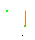
- To draw a circle or a rectangle, click at the start of the object and drag diagonally across the area in which you want the object to appear.
- To draw an arrow, click at the start of the arrow and drag from the beginning to the end of the arrow.
- To draw a freehand line, click at the start of the line and drag the cursor along the path of the line.
You can move and resize 2D markers easily. All you need to do is drag the green manipulators attached to the marker selected.
Note: It is possible to stack marker types:
- If you activate a marker type (e.g. line, ellipse, rectangle) and then activate another marker type without having first drawn a marker of the first type, then the second marker type will become active and the first marker type will be grayed out (the second type is stacked on top of the first type)
- After you create the marker of the second type, the first marker type will again become active and you can then create the corresponding marker (the second type has been removed from the stack and the first type is on top)
Note: Annotated views created in the clash viewer cannot be moved or edited.
-
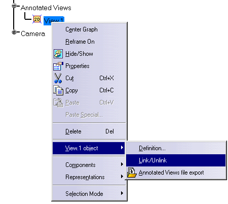
In the Specification Tree, right-click View.1 and select View.1 object -> Link / Unlink in the contextual menu.
The annotations you just created will no longer be linked to the view.
-
Rotate the view.
The annotations you created will still be visible.
-
To link the annotations once again to the view, repeat step 4.
-
Click the Text
 icon to annotate your view with text.
 -
In the view, click where you want to place the text.
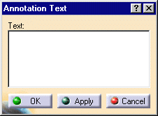
The Annotation Text dialog box and the Text Properties toolbar appear:
- In the menu bar, select Tools -> Options and then select the DMU Navigator tab.
- Click the 2D Marker Part Name Recognition radio button to activate the option.
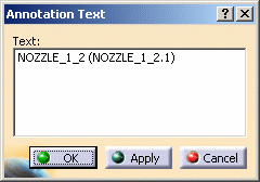
- In your DMU Navigator session, click the Text
 icon to add a text annotation and click on a Part on which you wish to
place the annotation (e.g. NOZZLE_1_2(NOZZLE_1_2.1).
That Part's name will automatically be the default annotation.
Inserting Symbols in Annotated Views (on Windows only)
You can insert symbols in annotated views.
- Choose the SymbC font. The symbol at the right of the Text Properties toolbar will now be selectable.
- Click the arrow and select a symbol from those proposed:
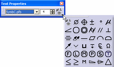
Using symbols forces you to change the font to SymbC and can create problems if text will be associated to the added symbol; the only font that can be used with symbol is SymbC.
-
Enter the desired text in the 2D text box and click Apply.
-
Change the size and style of annotation text if desired and click Apply.
-
When done click OK.
The text is added at the desired position.
-
To edit existing text, simply double-click.
-
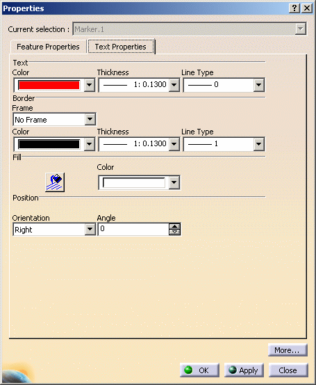
To change the Text properties, right-click the 2D text in the geometry and select Properties from the contextual menu displayed.
Double-clicking the Text icon in step 7 above will cause the first annotation text that you define to be conserved by default at each successive point at which you click. You exit from the loop by clicking the Text icon with a simple-click.
-
Make the desired changes, e.g. add a frame or change the text orientation.
Rotating 2D Text Annotations
Define the Angle parameter to be the number of degrees you wish to rotate the text annotation by entering the value in the Angle text-entry field or by clicking the value selection buttons.
-
When satisfied, click OK.
Modifying Annotation Properties
-
Select the Select
 icon to enter the selection mode.
 -
Right-click another object you've already drawn and select Properties from the contextual menu, or click the object then select Edit -> Properties from the menu bar.
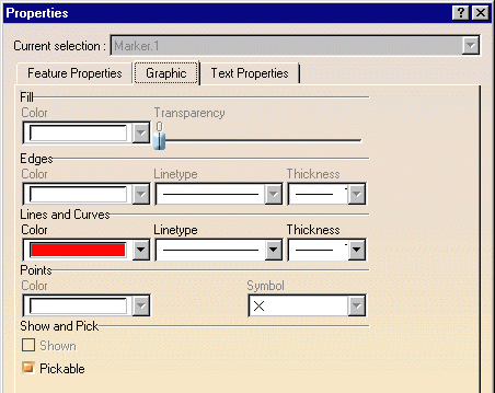
The Properties dialog box appears.
Note: Dynamic highlighting as you move your cursor over objects helps you locate them.
-
Click the Graphic tab to display the graphic properties of the current object.
-
Make desired changes (You can change the color, line type and line weight of the selected object.)
-
Click OK when done.
Exporting and Importing 2D Annotations in an XML file
-
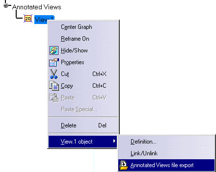
To export 2D annotations, in the Specification Tree, right-click View.1 and select View.1 object -> Annotated Views file export in the contextual menu.
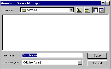
The Annotated Views file export dialog box appears.
-
Browse to the folder in which you wish to save the xml file containing the annotations.
-
In the File name text-entry field, enter the name of the file.
-
Click the Save button.
-
To import 2D annotations, in the menu bar, select Insert -> Annotated Views file import.
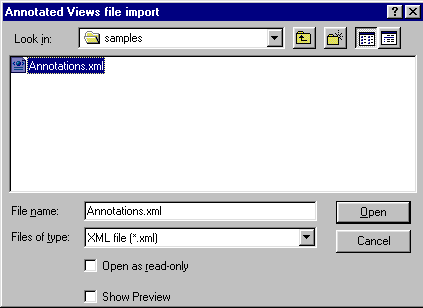
The Annotated Views file import dialog box appears.
-
Browse to the folder from which you wish to import an xml file containing annotations.
-
Select the desired file and click the Open button.
The annotated view contained in the xml file will be added to the annotated views listed in the Specification Tree.
Copying an Annotated View
-
To copy an annotated view, right-click the annotated view, select Copy in the contextual menu, right-click on the object in the specification tree under which you wish to copy the annotated view and select Paste in the contextual menu.
Note: The copy of the annotated view will have the same name as the original annotated view.
Deleting Annotations
-
To delete all annotations in the current view, select the Delete All Annotations icon
 .
.
You can also delete individual markers by right-clicking the object and then selecting Delete from the contextual menu.
![]()

