|
|
Molded
conventions are a set of rules that give default orientations when
placing structural elements, thereby ensuring structural continuity.
These conventions are defined in
the file
ShipStructureMoldedConventions.xml,
which is referenced in the Project Resource Management (PRM)
file.
The default location for this file is This file describes conventions for plates
and stiffeners of both Structure Functional
Design and Ship Structure Detail Design products. Plates
and stiffeners are oriented according to their
location in the hull and with respect to the midship or centerline.
Midship and centerline definitions are specified in another XML file
describing project parameters
(ProjectParameters.xml). NOTE: There is a DTD (Document Type Definition) file associated with this XML file. The DTD file enforces certain rules to which the XML file must adhere. If you make any change in the XML file, you must make sure they follow strictly the rules laid out in the DTD file. (You must not make any change in the DTD file.) The application will not function if you do not follow these rules. Also, the DTD file, by default, is located in the same directory as the XML file. If you change the location of ReferencePlanesSystem.xml then you must do the following:
|
|
Placing Structural ElementsThe system administrator can modify the following information: For Plates
|
||
 |
||
For Stiffeners
|
 |
|
|
||
For Stiffeners on Free Edge
Symbols UsedThe following is a list of orientations
that can be used to specify molded
conventions. This list is defined in
ShipStructureMoldedConventions.dtd. The
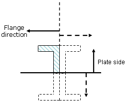
default location for this file is Symbols used for orientations (ThicknessOrient of plates,
PlateSideOrient and SectionOrient of stiffeners): Portside if FrontOrientation = Xm in ProjectParameters.xml
NR: Normal of support plane. |
||
 Anchor Point DefinitionAn entry from the ShipStructureMoldedConventions.xml file is reproduced below. It determines the anchor points that are available when placing the given object - in this case a stiffener.
<StiffenerClass Name="DeckStiffener" PlateSideOrient="HM"
SectionOrient="TI" Following are the values that can be used to define DefaultAnchorPoint and AnchorPoint Name: catStrBottomLeft |
||
2D View OrientationTo set the orientation of the object when it opens in the Sketcher change the settings in the following line of the ShipStructureMoldedConventions.xml file as explained below.
The valid values you can enter are as follows: XP: X Plus |
||
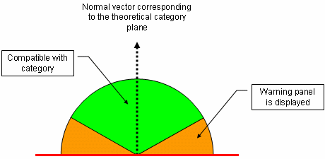
Selecting a SupportWhen creating stiffeners and plates, it is important to select a Support that is compatible with the selected Category. To ensure this, always select a Support that lies within the compatibility range of the theoretical vector of the selected category. As illustrated in the image below, a support selected in the green range is compatible with the theoretical vector of the category.
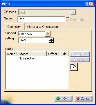
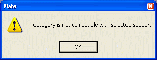
If you select a support beyond this range or normal to the vector, a warning message is displayed. In the image below, the selected Support (CROSS.66) is incompatible with the plate Category (Deck).
|
||
|
|
||


