-
Select the object for which you wish to create the trace.
The compass attaches itself to the base location of the object. 
The Simulation Trace dialog box appears: 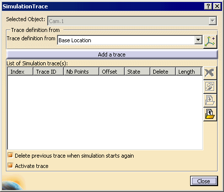

By default, the Delete previous trace when simulation starts again is enabled as a result of the option being selected on the Simulation Trace tab on the Tools > Options > DELMIA Infrastructure page. How you set the option on this dialog box will override the setting in Tools > Options. -
The trace appears on the List of Simulation trace(s): 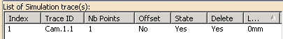
-
Click Process Simulation
 .
.The Simulation Trace dialog box disappears -
Click Run
 to see the simulation.
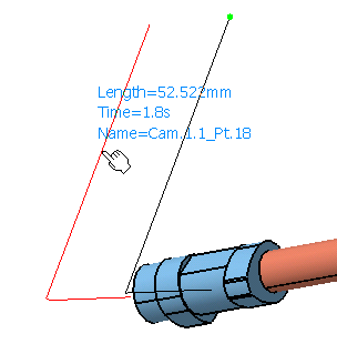
The trace appears on the geometry. Note that the track image (which is created by the Move Activity command) is the black line; the simulation trace (which runs from the base location) is in red. The color of the line is controlled by the Simulation Trace tab on the Tools > Options > DELMIA Infrastructure page. This line appears in red, for better contrast; the default value is white. 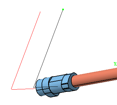
-
Run the mouse over the trace.
-
Click Simulation Trace
 again, and when the dialog box opens, select the previous trace.
The Simulation Trace options appear highlighted. 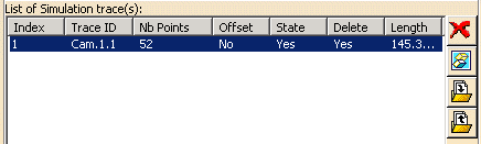
-
Click Hide/Show Trace
 ,
then click it again.
,
then click it again.The trace disappears then reappears on the geometry. -
A Save As dialog box appears. -
Navigate to the desired directory and save the trace as TraceCam1.1.xls.
-
The trace disappears on the geometry and from the dialog box. -
A File Selection dialog box appears. -
Navigate to the directory in which you stored TraceCam1.1.xls and select the Open button.
-
Select the Add a trace button.
The trace reappears in the Simulation Trace dialog box. -
Deselect Activate Trace.
-
Run Process Simulation to verify that no trace appears.
-
Click Simulation Trace
-
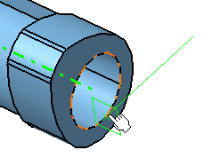
Select the Cam.
-
Reselect Activate Trace option, then select the Offset
 button.
The Offset dialog box appears. 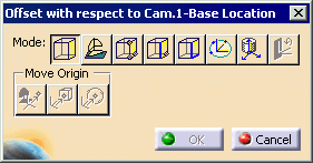
-
Use the buttons on Mode to select the offset from the base location.
-
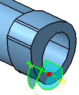
Select the location so that the compass snaps to it.
-
Select the Add a trace button, and then run Process Simulation
to observe the new trace.