 |
This procedure describes how to add a
visibility activity to a process.
A visibility activity can:
- hide one or more parts (which turns off the display of a part) or
- show one or more parts (which turns on the display so you can view
the part movement, if any)
- provide a transparent view of a part
- provide a different color for a part
- reset color or opaqueness of a part to the design values.
In addition to selecting discrete parts for visibility
activities, you can also select manufacturing
assemblies.
When visibility activities appear on the same level as other
activities, visibility activities remain in effect throughout a
simulation unless the process encounters visibility activities
countermanding their predecessors. When a visibility activity is a
child activity of another activity and the
simulation
options are set to Parent, the visibility activity
affects the simulation only during the parent activity; no additional
visibility activity is required to countermand effects of the initial
visibility activity. |
 |
-
Click Visibility Activity  from the Simulation Activity Creation toolbar.
| The Activity Creation Options dialog box appears
asking where to place the activity. |
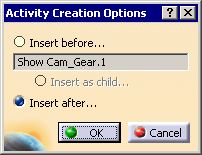 |
-
Select the location for the activity and click OK
.
| A visibility activity appears on the PPR tree (initially
named
SimulationVisibility), a preview window appears, and the Edit
Visibility Operation dialog box appears. |
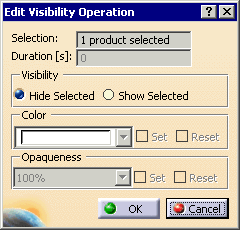 |
| By default, Hide Selected is checked. |
-
Select the part or parts whose visibility you want
altered.
| The part (or parts) appear in the preview window. |
 |
If you want to alter the visibility of more than one part, you
may do so by continuing to select parts. All of the parts
selected will appear in the preview window and the number of parts
listed in the selection box will increase. |
| |
If you inadvertently select the wrong part, you can de-select
the part or parts while the window is open by clicking on the part
a second time. |
-
Do you want the parts to remain visible?
- If no, click OK; the activity is added to the PPR
tree; the procedure is over.
- If yes, select Show Selected (the color and
opaqueness Set/Reset options will no longer be grayed
out).
|
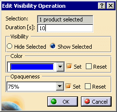
-
If you want the parts to remain visible do you want to
alter their color or opaqueness?
- If no, select the OK button; the activity is
added to the PPR tree; the procedure is over.
- If yes, set select one or both of the following:
- Set or Reset Color
- Set or Reset Opaqueness.
|
|
|
Setting the values changes the color and opaqueness from the
current values; resetting the values returns the color and
opaqueness back to the original design values. |
-
Use the data fields to alter the values you want
altered:
- If you want to alter the color, select a color from the
Color box.
- If you want to alter the opaqueness, select a percentage
from the Opaqueness.
- If you want to have the color and opaqueness changes occur
over a specified interval, in the Duration box, enter
the number of seconds in which you wish the change to occur.
|
 |
-
Click OK button; the activity is added to
the PPR tree.
|
|
The name of the activity starts with either hide or show and
then contains the part name. If you selected more than one
part, the first part selected is the name on the activity. |
| |
The image below shows the effect of altering the color to blue
and the opaqueness to 25%. |
| |
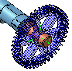 |
| |
If, in the Tools > Options > General > Display >
Performance dialog box, you have selected High
transparency quality, you can see differences among 75%, 50%, and
25% opaqueness setting. If you have selected Low,
the object will appear somewhat transparent, but different levels
of opaqueness will not be apparent.
See Tools > Options > General > Display > Performance
for more information. |
| |
If the color and/or opaqueness was already set on the parent
of the selected part, the change in color and opaqueness for the
child product is not visible for the user. The child is
displayed using the color /opaqueness of the parent. |
 |
For more details, see Displaying and Editing Graphic
Properties in the V5 Infrastructure User's Guide. |
|
|
|
In addition to selecting discrete parts for visibility
activities, you can also select manufacturing assemblies.
Selecting a single assembly instead of all its constituent parts is
often more efficient for users.
When you select a manufacturing assembly, the Selection
field in the Edit
Visibility Operation dialog box shows that one product has
been selected; it does not provide a count of the number of parts
selected. Similarly, when you select an assembly, on the PPR tree,
only the assembly node appears highlighted. In the 3D view, all
the parts of the assembly appear highlighted in the geometry.
If the children are changed for a manufacturing assembly that
is assigned to a visibility activity, their graphical properties are not
automatically changed. You have to run the simulation for the
corresponding visibility activity in order for the changes to be applied
on the new parts from the manufacturing assembly. |