Imported STL files or generated meshes may present some irregularities such as:
- Corrupted triangles, i.e. triangles that have the same vertex twice,
- Duplicated triangles, i.e. triangles that share the same three vertices,
- Inconsistent Orientation, i.e. triangles that can not be oriented consistently with respect to each other,
- Non-manifold edges, i.e. edges shared by more than two triangles,
- Non-manifold vertices, i.e. vertices shared by two or more connected shells.
A mesh may also present some structural problems such as:
- Orientation problems, i.e. all the triangles are not oriented in the same direction,
- Isolated triangles, i.e. triangles belonging to small connected areas
of the mesh,
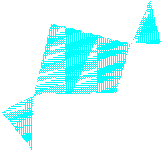
- Disconnected zones, i.e. the mesh is made of several disconnected
zones,
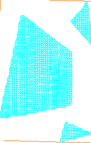
- Triangles with long edges.
- Thin triangles.
Mesh cleaner proposes two families of treatments on such meshes:
- Deletion, i.e. visualization and deletion of corrupted or duplicated
triangles,
of triangles with an inconsistent orientation, of non-manifold edges, or non-manifold vertices,
of isolated triangles and triangles with long edges. - Structure, i.e. re-orientation or split.
Structure problems must be processed separately.
Open MeshCleaner2.CATPart from the samples directory for Edition.
Deletion
-
Click Mesh Cleaner
 and select the mesh.
The dialog box is displayed. -
In the Deletion tab, click Analyze.
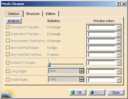
Once the analysis is completed, the lines corresponding to the problems found become active.
The Statistics column is updated with the number of cases found.
Here, only non-manifold vertices have been found, and there are 5 such vertices.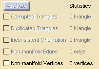
-
You can visualize the problems found:
Select the check boxes of the problems you want to visualize. By default, they are displayed in white.
You can choose another color from the Preview colors list.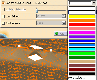
-
For Isolated Triangles, use the slider to define the maximum number of triangles that a disconnected area may contain.
If you set the slider to n, all the areas containing between 1 and n triangles will be visualized, then deleted.
The limit values of the slider are defined according to the mesh. -
For Long Edges, use the spinner to define the maximum allowed length edge of triangles.
All triangles with edges longer than this value will be deleted. -
Click Apply to delete the unwanted elements and OK to exit the action and save the processed part.
Structure
-
Click Mesh Cleaner
 and select the mesh.
The dialog box is displayed. -
In the Structure tab, select the Orientation check box.
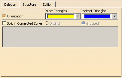
The triangles are displayed as direct or indirect, in the color of your choice.
Those that are candidates for a re-orientation are shown by an arrow:
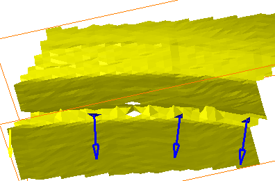
Click the arrow of the triangles you want to re-orient.
The color and the direction of the arrow change:
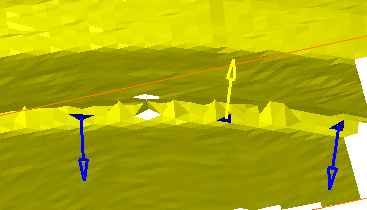
Click Apply. The triangles are re-oriented, if that is possible.
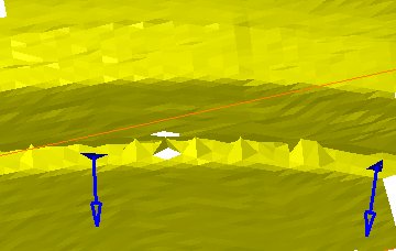
Note that a contextual menu is provided on each arrow:
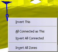
Invert This:
Inverts the orientation of the area linked to the arrow.
Equivalent to clicking the arrow.All Connected as This:
Applies the same orientation to all the areas connected to that linked to the arrow.Invert All Connected:
Inverts the orientation of the area connected to the arrow, and of all the areas connected to it.Invert All Zones:
Inverts the orientation of all the mesh areas. -
Select the Split in Connected Zones check box.
If there is only one zone, split is not possible and the check box cannot be selected.
If connected zones are found, the text box below is updated with the number of connected zones found.
Choose to split them in Distinct zones or in one Grouped zone.
Click Apply. SubMesh.x elements are then created in the specification tree. -
Click OK to save the processed part and exit the action.
![]()