 |
-
From the Layout Tools/Snap
toolbar, click
Snap Two Parts
 . .
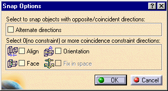
| The Snap Options dialog box appears. |
 |
-
Select the item to be snapped.
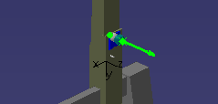
| A green arrow appears showing the current orientation of the
item. |
 |
-
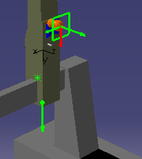
Move the cursor down to where the item should go.
| An arrow appears showing the orientation assumed for the item.
In the illustration below, a probe head is getting snapped to a
CMM. |
 |
-
Click on the green circle at the base of the arrow.
| The Snap Options dialog box appears. |
 |
-
(Optional) Select one of the check
boxes.
When you create constraints, V5 creates a new coordinate axis.
Because CGR data has no axis
information, new CATParts are created automatically if you
select CGR files for snapping/snapped geometries. |
-
Click OK.
Once the items are snapped,
Snap Two Parts
 is no longer highlighted.
 |
|


