Structure of the Generative View Styles
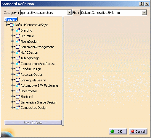
This file is structured as a tree. Under the Standard> DefaultGenerativeStyle nodes, there are several sub-nodes:
- the Drafting node is devoted to customizing generative view styles for views generated from any 3D workbench in general. For more information, refer to Setting General Generative View Style Parameters.
- the other nodes are devoted to customizing generative view styles for views generated from given workbenches. For example, the SheetMetal node is devoted to customizing generative view styles for views generated from the Generative SheetMetal Design workbench. For more information, refer to Setting Workbench-Specific Generative View Style Parameters and/or to the workbench's User's Guide.

Customizing Generative View Style Parameters
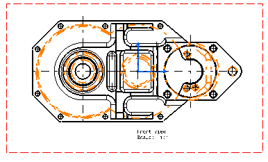
The pre-defined DefaultGenerativeStyle.xml file specifies that hidden edges should be displayed in black, using a specific linetype and thickness. You will modify these parameters so that hidden edges are displayed in orange, for example, and using a different linetype and thickness.
![]()
Select Tools> Standards to launch the Standard Definition dialog box. Choose the generativeparameters category, and then open the DefaultGenerativeStyle.xml file from the drop-down list.
-
In the editor, expand the following nodes successively: Standard> DefaultGenerativeStyle> Drafting> ViewDressup> GeneratedGeometry> HiddenEdges.
-
Select the Color parameter.
-
Set the color to orange, for example by choosing another color from the drop-down list in the right-hand pane.
-
Select the Linetype parameter.
-
Set the linetype to 4, for example by choosing another linetype number from the drop-down list in the right-hand pane.

Linetypes are defined in Tools> Options> General> Display> Linetype tab. -
Select the Thickness parameter.
-
Set the thickness to 2, for example by choosing another thickness number from the drop-down list in the right-hand pane.

To define a thickness, select Tools> Standards to launch the Standard Definition dialog box. Choose the drafting category, and then open the [StandardFile].xml file from the drop-down list. In the editor, expand the following nodes successively: Standard> [StandardFile]> Line Thicknesses. -
Click OK to save your modifications and exit the standards editor.
-
Define a new drawing sheet.
-
Create a front view. The view is generated, taking into account the parameters you defined.
