For the purpose of this scenario, you will create a front view using generative view styles, but you can use generative view styles to create any type of view.
-
Go to Tools > Options > Mechanical Design > Drafting > Administration tab, and clear the Prevent generative view style usage check box. This activates the generative view style functionalities.

If you deactivate the Prevent generative view style usage option the 3D colors option is not available in the view properties any more. -
Click Front View
 in the Views toolbar (Projections sub-toolbar). The Generative view style
toolbar is automatically displayed.
 -
Select one of the generative view styles available from the list. For example, select DefaultGenerativeStyle. The parameters defined in this file will be used when creating the view.
- The generative view styles available in the list refer to the external files that can be found in specific directories as explained in Administering Generative View Styles and Standards and also refer to the generative view style files embedded in the drawing. In case those files have the same name, only the embedded file is taken into account.
- The generative
view style used for creating a view is stored in the CATPreferences file and is displayed as the default option when
creating the next view, if the generative view style is valid.
This persistence of the last used generative view style, is also
applicable across two CATIA sessions.
The recently used generative view style moves up to the first position in the drop-down selection list. - If there is no valid last used generative view style available the drop-down list shows the first option in alphabetical order as the default option.
- The Generative view style toolbar is displayed when
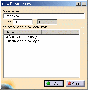
creating most view types. However, when creating advanced front
views, this toolbar is not displayed. Instead, the View
Parameters dialog box (which is displayed when creating
advanced front views) features an additional list, which enables
you to select a generative view style.

-
In the 3D window, select a plane of the 3D part or a plane surface, to define the reference plane.
-
Click inside the sheet to generate the view.
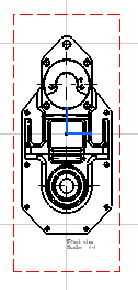
The view is created using the selected generative view style. In our example, vivid edges are projected in black. Note that you may obtain a different result. This result depends on the parameters defined in the generative view style you selected.

![]()