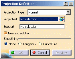
You can project:
a point onto a surface or wireframe support
- wireframe geometry onto a surface support
any combination of points and wireframe onto a surface support.
Open the Projection1.CATPart document.
-
Click Projection
 .
. -
Select the element to be Projected.
You can select several elements to be projected. In this case, the Projected field indicates: x elements. 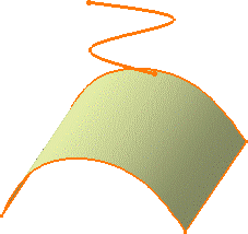
-
Select the Support element.
-
Use the combo to specify the direction type for the projection:
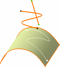
- Normal: the projection is done normal to the support element.
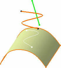
- Along a direction: you need to select a line to take
its orientation as the translation direction or a plane to take its
normal as the translation direction.
You can also specify the direction by means of X, Y, Z vector components by using the contextual menu on the Direction field.
-
Whenever several projections are possible, the nearest projection can be kept by checking Nearest Solution.
If this option is not checked, the Multi-Result Management dialog box opens to let you choose the solution. Check Keep all the sub-elements to have a complete solution.

If the elements have the same distance to the support, an error message is issued. This distance corresponds to the maximum distance between a point on the projected element and its projection onto the support.
-
Click OK to create the projection element.
The projection (identified as Project.xxx) is added to the specification tree.
Smoothing Parameters

- None: deactivates the smoothing result
With support surface: the smoothing is performed according to the support. As a consequence, the resulting smoothed curve inherits support discontinuities. - Tangency: enhances the current continuity to tangent continuity
- Curvature: enhances the current continuity to curvature continuity
-
You can specify the maximum deviation for G1 or G2 smoothing by entering a value or using the spinners.
If the element cannot be smoothed correctly, a warning message is issued.
Moreover, a topology simplification is automatically performed for G2 vertices: cells with a curvature continuity are merged.

Only small discontinuities are smoothed in order to keep the curve's sharp vertices.
Without support surface:
-
3D Smoothing: the smoothing is performed without specifying any support surface. As a consequence, the resulting smoothed curve has a better continuity quality and is not exactly laid down on the surface.
As a consequence, you may need to activate the Tolerant laydown option. Refer to the Customizing General Settings chapter.
This option is available if you previously select the Tangency or Curvature smoothing type.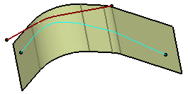
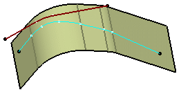
With 3D smoothing option checked With 3D smoothing option unchecked
![]()
