- the points space coordinates
- the points through which the curves pass
- the curves used as profiles for the multi-sections surface.
Therefore this capability is available with WindowsTM only.
Open any .CATPart document containing a Geometrical Set or an Ordered Geometrical Set.
-
Open the ElementsFromExcel.xls file from the Samples directory into Excel, and enable the macros.
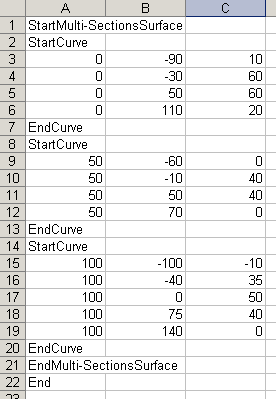
The document looks like this: 
It contains: - instructions, such as StartMulti-SectionsSurface and EndMulti-SectionsSurface, StartCurve and EndCurve between which other instructions or numerical data are given.
- numerical data that are point space coordinates: X, Y, Z respectively from the left to the right
- a final End instruction
In the above example, a multi-sections surface is to be created based on three curves. The first and second curve pass through four points, and the third curve passes through five points.
The elements will be created from top to bottom, i.e. the four points of the first curve will be created, then the curve itself, then the points making up the second curve and the latter itself, and so forth.

You can add rows to create more elements or delete rows to edit elements or delete them (point), then save the spreadsheet. -
From Excel, select Tools > Macro > Macros from the menu bar.
The Macro dialog box is displayed. -
Select the Feuil1.Main macro

-
Click Run.
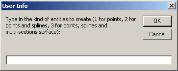
The User Info dialog box is displayed. 
-
Key in the type of element to be generated:
-
Click OK.
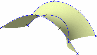
The elements (points, curves, and multi-sections surface) are created in the geometry. The specification tree is updated accordingly. 

- The Generative Shape Design or Wireframe and Surface workbench needs not to be loaded, provided a CATIA session is running and a .CATPart document is loaded.
- The curve definition is limited to 500 points, and the multi-sections surface definition to 50 splines, with the delivered macro. This can be modified using the Excel macro edition capabilities.
![]()