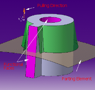
In case you do not want to draft the whole part, optionally select what we call "functional faces": these faces identify the faces you do not want to draft.
Using AutoDraft is therefore a good way of drastically reducing the time spent on drafting.
-
Click Automatic Draft
 in the Advanced Dress-up Features toolbar
 .
.
The Automatic Draft Definition dialog box appears.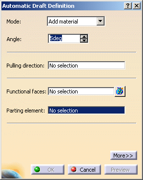
-
Optionally, click More to expand the dialog box and display images helping you define your specifications.
-
The Mode field lets you specify a mode among two possible ones:
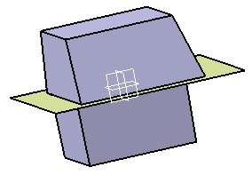
- Add material: adds the minimum amount of material to the part to perform the draft operation. This implies that the part will be enlarged on the parting element. The neutral faces are automatically computed in this case, detected among the body faces, on the side defined by the pulling direction.
- Remove material: removes the minimum amount of material from the part to perform the draft operation. This implies that the part will be kept unchanged on the parting element. So the neutral elements contain the parting element.
Help images reflect the computation mode you select. For the purpose of our scenario, keep Add material.
-
Right-click on the Pulling direction field and set the Pulling direction as Z Axis. The pulling direction defines the side of the parting element to be drafted.
-
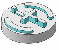
The Functional Faces field lists the manufactured faces that are not to be drafted. The selected faces turn purple, indicating that they will not be drafted.
-
Keep 15deg as the draft angle value. The minimum angle value between the surface of the part and the pulling direction is the draft angle value.
-
Select Extrude.1 as Parting element.
-
Check OK to confirm.
A new dialog box appears, indicating the operation progress. In case you want to interrupt the operation, just click Cancel. -
The drafts are displayed in the geometry area:
-
The Automatic draft feature is subjective to the presence of the Cast and Forged Part Optimizer product license. A warning message is displayed indicating the limited use of this feature due to non-availability of CFO product license.
- You cannot select a neutral element that is not intersecting the face to draft.
-
You should provide a parting element large enough in order to intersect the whole draft skin. Particularly, when material is added the parting element can not be a set of faces from the body to draft because it is not large enough.
-
The parting should also be a connex and finite skin. This skin should be orientable.
-
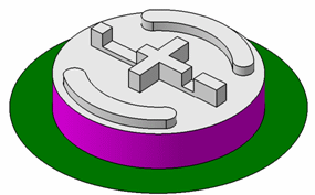
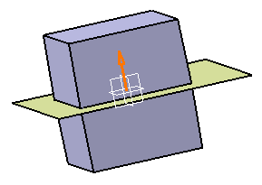
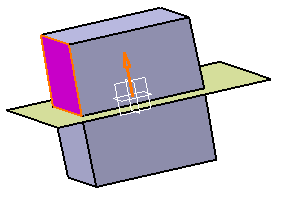
The parting element is mandatory if the remove material mode is chosen. It is often needed for add material mode it can however be omitted if all the faces from the input body that cross the parting are functional faces, like for example in this case (the functional faces are the pink faces):