Inheritance for Assembly objects
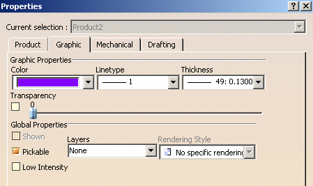
The following properties can be inherited: color, transparency, line type and line weight. This inheritance can be deactivated by doing one of the actions below depending on the property you do want to inherit:
- select No Color in the Color list
- select No Linetype in the Linetype list
- select No Width in the Thickness list
- clear the option next to the Transparency slider.
For detailed information on graphic properties applied to products, refer to "Managing Graphic Properties in Products" in the Version 5 - Product Structure User's Guide.
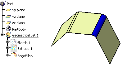
Inheritance for Mechanical Modeler objects
- When a mechanical object (a pad, for instance) has been assigned a
color, this color is used to display the object. Otherwise, the object is
displayed using the color of its father element (i.e. the part body).
To reset the inheritance from the father to the children, select Reset properties from the Edit menu or from the pad's contextual menu. Bear in mind that this command cancels any local modification applied to the graphic properties of the pad (including color and transparency) - The following properties are set at the part body level and cannot be inherited: point symbol, line thickness and line type.
Materials
When a material has been applied onto a part with Material
selected in View > Render Style > Customize View (or with
Shading with Material
![]() selected in the View toolbar), the graphic properties defined in
the Properties dialog box have no impact on the part display
anymore.
selected in the View toolbar), the graphic properties defined in
the Properties dialog box have no impact on the part display
anymore.
As a consequence, if you need to modify the transparency, for instance,
this must be done in the material properties. For detailed information on
modifying material properties and on materials in general, refer to the
Version 5 - Real Time Rendering User's Guide.
-
Select the object whose graphic properties you want to display.
The object to be selected when using the Part Design application is the part body item in the specification tree. -
Select Edit > Properties command (or press ALT+Enter) or right-click then select Properties.
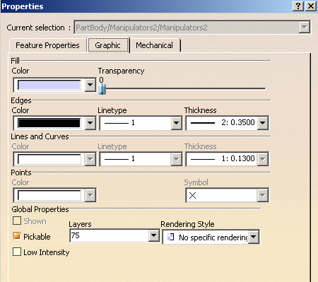
A Properties dialog box similar to the one below is displayed (note that the tabs might be displayed in a different order depending on the object you select): 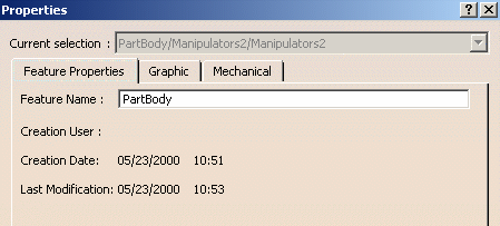
-
Click the Graphic tab to display the graphic properties of the current object:
-
To set object colors, use the Color list.
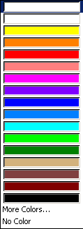
A list appears containing: - a blank color box (No Name)
- a list of sixteen default colors from the color palette, ready for use
- More Colors...
- No Color (for Assembly objects only).

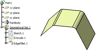
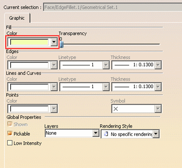
No Color lets you deactivate the color inheritance for Assembly objects. You can then apply a color onto a face without having to modify the product color. To do so: - select the product
- access the Properties dialog box
- choose No Color in the Color list
- select the face onto which you want to apply the color
- access the face's graphic properties
- select the desired color from the Color list.
-
Select the desired color.
-
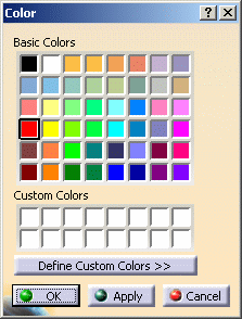
To access more colors, or to create your own colors, click More Colors... at the bottom of the list to access the Color palette:
-
Click Define Custom Colors >> to display the full color palette and color customization tools:
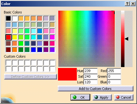

The colored area with the cross represents a color spectrum. Drag the cross inside the spectrum to instantaneously change the color in the small box below the spectrum.
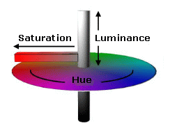
The HSL (Hue, Saturation and Luminance) and RGB (Red, Green and Blue) values vary according to where the cross is located. You can also enter HSL and RGB values in the fields provided to suit your exact color specifications.
HSL is an alternate model to RGB model for color specification and is illustrated by the scheme below:
Move the arrow up or down to vary the brightness of the custom color: 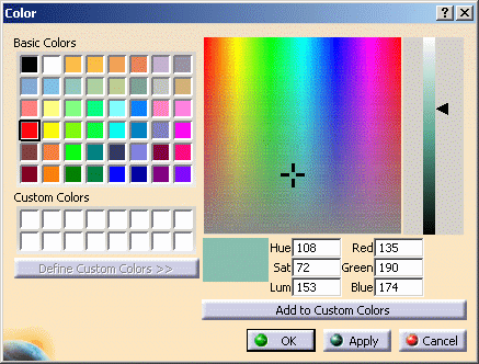
-
Once you are happy with the color, click one of the free boxes in the Custom Colors area, then Click Add to Custom Colors to add the customized color.

-
Click on the custom color, then OK.
The color is now displayed in the Color fill box of the Graphic Properties tab. -
Click Apply in the Properties dialog box.
The color of the selected object is changed. -
To make the part more or less transparent, drag the Transparency slider to set the appropriate value (between 0 and 255).
Note that you can set either of two transparency modes via the Performance tab in Tools > Options: - Screen Door
- Alpha Blending
For more information, refer to Customizing Performance Settings.
As far as .asm documents are concerned, you can select or clear the Transparency check box to apply or not a transparency inheritance independently from the color of the selected object. -
To set color edges on parts, use the Color list for edges and proceed the same way.
-
To set edge line type and thickness, use the appropriate lists.
-
If you have selected a line or a curve, you can set the line and curve color, the linetype and thickness the same way as for parts.
-
If you have selected a point, you can set the point color in the same way as for parts. To select the symbol used to represent the point, select the symbol from the Symbol list.
-
In the Global Properties area, the Shown check box indicates if the object is always visible (i.e. in Show mode) or always hidden (i.e. in No Show mode).
This check box is displayed for information only and cannot be modified.For more information about the show and no show modes, refer to Hiding and Showing Objects. -
Still in the Global Properties area, select the Pickable check box if you want the object to always be selectable.
-
The Layer list indicates the number of layers the selected objects are assigned to. Otherwise (when nothing is selected) it indicates the current layer.
When pointing to the Layer list, a tootip indicates whether the layer definition location is stored in the document or in the user settings (i.e. the CATSettings directory).
However, bear in mind that this tooltip is displayed for information only, you cannot modify the storage location which has been set as explained below:- for CATProduct documents, the definition is stored in the user settings
- for CATPart documents, the definition (if there is one) is stored in the document. If no definition is stored in the document, the CATPart documents use the definition stored in the user settings
- for CATDrawing documents, the definition is stored in the document.
Use the list to choose among the list of named layers and assign the chosen layer to the selected objects: None, 0 General, 1-999 (according to the number of layers in the Layer list). For more information, refer to Assigning Objects to Layers. The Layer box also contains the Other Layers... command which lets you create your own named layers. Refer to Creating New Layers for more details.
-
Select the Low Intensity check box to apply the low-intensity color to the selected element. This property enables you to filter the visualization of any geometry by applying a specific color.
By default, the color to be applied to low-intensity elements is "dark green" but you can modify it in Tools > Options > General > Display > Visualization. Elements can be put in low-intensity state by: - selecting the Low Intensity check box in the Graphic tab of the Properties dialog box
- right-clicking any view from the geometry area or the specification tree then selecting Background > Low-intensified when working with the 2D Layout for 3D Design product. Refer to the dedicated documentation for more information
- clicking Low intensity background
 in the Visualization toolbar (when working with the
Sketcher product) or in the Tools toolbar
(e.g. when working with the Generative Shape Design or
Wireframe and Surface product). Refer to the dedicated
documentation for more information.
It is possible to keep the low-intensity state for 2D or 3D objects displayed in Shading with Material rendering style. This means that when you apply the low-intensity state to objects onto which materials have been applied, the low-intensity state is kept even though the elements are visualized in Shading with Material. This is illustrated by the examples below showing two parts onto which materials have been applied:


Low Intensity check box is cleared
The materials applied onto the two parts
are displayedLow Intensity check box is selected
The materials are not displayed anymore ; they are overriden by the low-intensity colorAs soon as you clear the Low Intensity option, the materials are displayed. -
The Rendering Style list lets you select the rendering style you want to apply to the selected element, provided that this element supports rendering styles.
This rendering style will then be used to visualize the object independently from the rendering style applied to the 3D window when using the Enable object view mode visualization mode.Note that this option is identical to the one provided in the Graphic Properties toolbar.
Rendering styles can be applied only on .CATPart documents or on .CATPart documents embedded in .CATProduct documents:
-
Part Body
You can apply a rendering style to each body composing the part body and this, even if a body is embedded into another one.
All the elements gathered in the part body or in the body inherit the rendering style of their parent. As a consequence, you cannot apply a rendering style to the child solid features (such as a pad or a fillet) -
Geometrical Set
You can apply a rendering style to the Geometrical Set as a whole and to each child feature in the graph ; each feature may be applied a different rendering style. If no rendering style has been applied to a feature, this feature will be displayed with the rendering style applied to the father element or, if no father exists, with the rendering style of the viewer used to display the feature
-
Shape Body
The behavior is identical to the one of the Geometrical Set except that different child features may share the same visual representation and therefore, the same rendering style.
By default, no rendering style is applied but you can choose among the following styles:
-
No Specific Rendering
This is the default mode. You can use it to remove a rendering style that has been previously applied
-
Transparent
Displays the selected element in transparent mode:
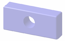
-
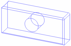
Wireframe
Displays the selected element in wireframe mode:
-
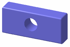
Shading
Displays the selected element in shading mode:
-
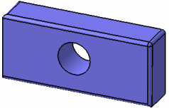
Shading with Edges
Displays the selected element in shading with edges mode:
-
-
Click Apply or OK to confirm.
About Automation
Macros are provided to retrieve and change the following graphic properties:
- color
- opacity (i.e. transparency)
- line type
- line thickness
- symbol
- show
- pick
- layers.
Refer to "Infrastructure Automation Objects" in the Enterprise Architecture Automation - 3D Visualization documentation for detailed information.
![]()
