This task explains how to access company standards files (available in .xls format) in order to define methods for joggle and sides compensations. The methods described in this task apply to joggles relying on a flange with a base feature (either a web or a flange) without joggles.
Open a new document.
-
Click the Sheet Metal Parameters icon
 .
The Sheet Metal Parameters dialog box is displayed.
 -
Select the Sheet Standards Files... button. The File Selection window is displayed.
-
Indicate the path to the Sheet Metal methods.
Method 1
- the end of the part:
- near the end of part (case 1)
- not near the end of part (case 2)
- the position of other joggles:
- twin joggles (case 3)
- double joggle near the end of part (case 4)
- double joggle not near the end of part (case 5)
How the different cases and the deformation are managed
Six values are used in the following description: C1, C2, C3, C4, C5, Ra. These values are defined in a design table. The path to this design table is defined in the Std_Method1.xls file.
Here is an example of a design table:
|
|
|
[...] |
|
|
|
[...] |
[table continued below]
| [...] |
|
|
|
| [...] |
|
|
|
Case 1
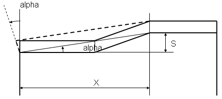
- The parameters necessary for performing the modifications are as
follows:
- The parameter of the feature is: S (joggle depth)
- Some values are computed to define the type of deformation: alpha, X.
- The parameter definition and links are as follows:
- This case is applied if X < C1.
- C1 is defined with a constant value.
- This deformation is performed as follows:
- The alpha angle is computed from S and X ( tangent(alpha) = S / X ).
- The side and the EOP are then rotated with the alpha angle. The center of rotation is the intersection between the BTL on the flange and the side.
Case 2
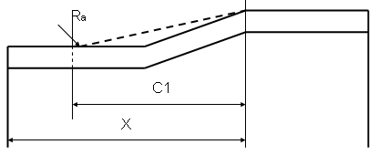
- The parameters necessary for performing the modifications are as
follows:
- The values of the modification are: C1, Ra.
- The parameter definition and links are as follows:
- This case is applied if X > C1.
- C1 is defined with a constant value.
- Ra is defined with a constant value.
Case 3

- The parameters necessary for performing the modifications are as
follows:
- The values of the modification are: C2, C3, C4, Ra.
- A value is computed to define the type of deformation (table) to apply: X.
- The parameter definition and links are as follows:
- This case is applied if C3 > X > C2.
- Then: a = (X - C4) / 2.
- C2, C3 and C4 are defined with a constant value.
- Ra is defined with a constant value.
Case 4

- The parameters necessary for performing the modifications are as
follows:
- A value is computed to define the type of deformation (table) to apply: X.
- The parameter definition and links are as follows:
- This case is applied if C4 > X.
- C4 is defined with a constant value.
Case 5

- The parameters necessary for performing the modifications are as
follows:
- A value is computed to define the type of deformation (table) to apply: X.
- The parameter definition and links are as follows:
- This case is applied if C5 > X.
- C5 is defined with a constant value.
Method 2
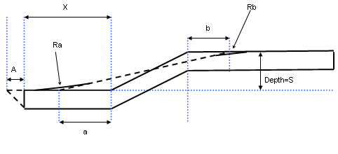
- The parameters necessary for performing the modifications are as
follows:
- Input parameters for joggle compensation:
- Material Thickness: t
- Joggle parameters: S (joggle depth)
- Distance between the joggle and the side of the flange: X
- Output parameters:
- Offset from start of joggle: a
- Offset from end of joggle: b
- Flange side compensation: A
- Radius on start and end of joggle compensation: Ra, Rb
- Input parameters for joggle compensation:
- The parameter definition and links are as follows:
- A, a, b, Ra, Rb are defined from two design tables. The paths to
these design tables are defined in the Std_Method1_2.xls file.
Std_Method1_2.xls also contains the path to each defined thickness.
For each value of a material (therefore for each thickness) in Std_Method1_2.xls, two tables defining compensation values may be defined:
A first table defining A, depending on S:
JoggleCompensation_SMax
JoggleCompensation_a
JoggleCompensation_b
[...] 0.8
a (0.8)
b (0.8)
[...] 1.1
a (1.1)
b (1.1)
[...] 1.5
a (1.5)
b (1.5)
[...] [table continued below]
[...] JoggleCompensation_Ra
JoggleCompensation_Rb
[...] Ra (0.8)
Rb (0.8)
[...] Ra (1.1)
Rb (1.1)
[...]
Ra (1.5)
Rb (1.5)
- A, a, b, Ra, Rb are defined from two design tables. The paths to
these design tables are defined in the Std_Method1_2.xls file.
Std_Method1_2.xls also contains the path to each defined thickness.
The third line should be read as follows: if (1.1<SMax≤1.5) then a=a (1.5); b=b(1.5); Ra=Ra (1.5) and Rb=Rb (1.5)
|
|
|
|
|
|
|
|
|
|
|
|
|
|
|
|
|
|
|
|
|
The fourth line should be read as follows: if (0.8<SMax≤1.1) and (X" (0.8)<XMax≤X(1.1)) then A=A (1.1)
Definition of Side Compensation
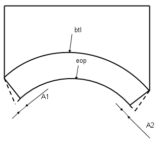
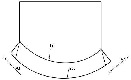
- The parameters necessary for performing the modifications are as
follows:
- The values of the modification are: A1, A2
- The type of compensation can be:
- None: no compensation is applied
- Automatic (for symmetric flanges): A1 = A2, so that the length of the flatten eop = the length of the folded eop
- Manual: Angle: the deformation is computed according to an angle
- Manual: Length: the deformation is computed according to a length parallel to the btl.
-
Choose the appropriate type of compensation.
-
Click Ok.
In the Sheet Metal Parameters dialog box, if you chose Method 2, the Design Table icon
appears opposite the Thickness field. You can click this icon to edit the design table.
![]()