Portal |
Visualization |
Modifying Object Graphical PropertiesUsing the CATIVisProperties interface |
| Use Case | ||
AbstractThis article shows how to use the CATIVisProperties interface to modify the graphical aspect of an object. |
This article shows how to use the CATIVisProperties interface to retrieve or set the graphical properties for CATIA V5 features. This interface contains five main methods:
GetPropertiesAtt, retrieves the propertiesSetPropertiesAtt, modifies the propertiesThese two methods function on the same principle: there is a CATVisPropertiesValues instance and two keys:
These two keys specify the valid attributes on the instance.
ResetPropertiesAtt, resets the properties to follow the
standardGetStandardProperties, retrieves the standard propertiesThese two methods, as the two above, also work with the same two keys. The reset is done on a feature for a given type of geometry and for a given type of property.
IsGeomTypeDefined, tells if a given type of geometry is
recognized by the feature.In this article you will learn to:
[Top]
CAAGviApplyProperties is a use case of the CAAGeometryVisualization.edu framework that illustrates Visualization and GeometryVisualization framework capabilities.
[Top]
The goal of this use case is to change the graphic properties of some GSM
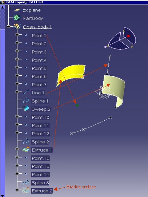
features.It is based on a delivered Part document called "CAAProperty"
[Fig.1], located in the CAAGeometryVisualization.edu/InputData
directory. This document contains the following elements:
| Point.1 | a green,full square point |
| Line.1 | a solid, pickable line |
| Extrude.1 | a yellow surface |
| Sweep.2 | a surface with standard color |
| Extrude.2 | a hidden surface |
|
By using the CATIVisProperties interface, these elements become:
| Point.1 | a red, cross point |
| Line.1 | a dashed,no-pickable line |
| Extrude.1 | a surface with standard color |
| Sweep.2 | a transparent surface with red edges |
| Extrude.2 | a visible surface |
The modified document is saved in the
"CAAPropertyWithNewProperties.CATPart" document. [Fig
2]
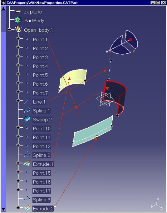 |
For the Line.1feature, try going over on the line, it is not highlighted. For the Sweep.2 feature, turn the model, you can see through the surface because it is transparent.
[Top]
To launch CAAGviApplyProperties , you will need to set up the build time environment, then compile CAAGviApplyProperties along with its prerequisites, set up the run time environment [1]. Then execute the following command:
mkrun -c CAAGviApplyProperties InputPath [OutputPath]
where:
CAAProperty.CATPart
document included in the directory CAAGeometryVisualization.edu/InputData
InstallRootDirectory/CAAGeometryVisualization.edu/InputData
InstallRootDirectory\CAAGeometryVisualization.edu\InputDataCAAPropertyWithNewProperties.CATPart
will be stored. If this path is empty, the output file is created in
the current directory.[Top]
The CAAGviApplyProperties use case is made of a main program located in the CAAGviApplyProperties.m module of the CAAGeometryVisualization.edu framework:
| Windows | InstallRootDirectory\CAAGeometryVisualization.edu\CAAGviApplyProperties.m\ |
| Unix | InstallRootDirectory/CAAGeometryVisualization.edu/CAAGviApplyProperties.m/ |
where InstallRootDirectory is the directory where the CAA CD-ROM
is installed.
[Top]
The main steps of CAAGviApplyProperties are:
[Top]
CAAGviApplyProperties begins by creating a session, and opening the
"CAAProperty" Part document. Next, it retrieves the root container of
this Part as a pointer to CATIPrtContainer, pIPrtCont. This
is the usual sequence for loading a Part document.
Thanks to the GetPart method on the root container we retrieve
the Mechanical Part feature handled by the smart pointer spPart.
[Top]
The five features are inside the same Open Body:
...
  CATLISTV(CATBaseUnknown_var) surfBodies;

  CATIPartRequest *pPartAsRequest = 0;
  rc = spPart->QueryInterface(IID_CATIPartRequest, (void**)&pPartAsRequest) ;

  if ( SUCCEEDED(rc) )
  {
     const CATUnicodeString stdContext(" ");

     pPartAsRequest->GetSurfBodies(stdContext, surfBodies);

     if ( (1 != surfBodies.Size()) && ( NULL_var != surfBodies[1]) )
     {
        ...
        return 1 ;
     }

     pPartAsRequest->Release();
     pPartAsRequest = NULL ;
  }
...
|
The CATIPartRequest interface pointer is retrieved on the Mechanical
Part, pointed to by the spPart smart pointer, The GetSurfBodies
method returns the list of the Open Bodies contained in the Part document, and
in the case of the "CAAProperty" document, there is only one Open
Body, so the size of the list is 1.
The features inside the Open Body, pointed to by surfBodies[1],
are retrieved thanks to the CATIDescendants interface:
... CATIDescendants * pIDescendantOnOpenBody1 = NULL ; rc = surfBodies[1]->QueryInterface(IID_CATIDescendants, (void**)&pIDescendantOnOpenBody1) ; ... //The point - Point.1 CATISpecObject_var ThePoint = pIDescendantOnOpenBody1->GetChildAtPosition(1); // The line - Line.1 CATISpecObject_var TheLine = pIDescendantOnOpenBody1->GetChildAtPosition(8); // The yellow surface - Extrude.1 CATISpecObject_var TheExtrude1Surface = pIDescendantOnOpenBody1->GetChildAtPosition(15); // The sweep surface - Sweep.2 CATISpecObject_var TheSweep2Surface = pIDescendantOnOpenBody1->GetChildAtPosition(10); // The hidden surface - Extrude.2 CATISpecObject_var TheExtrude2Surface = pIDescendantOnOpenBody1->GetChildAtPosition(20); ... pIDescendantOnOpenBody1->Release(); pIDescendantOnOpenBody1 = NULL ; ... |
The position of each element has been determined in an interactive session.
[Top]
The point, Point.1, is represented by the ThePoint smart pointer
in the code.In the above picture [Fig.1], you can see that
this point is green and its symbol is a full square. But before changing its
graphical properties, we verify its current properties:
Is it a green point ?
...
  CATIVisProperties * pIPropertiesOnPoint = NULL ;
  rc = ThePoint->QueryInterface(IID_CATIVisProperties, (void**)&pIPropertiesOnPoint) ;
  ...

  CATVisPropertiesValues               MyPropertyOnPoint ;
  CATVisPropertyType PropTypeOnPoint = CATVPColor ;
  CATVisGeomType GeomTypeOnPoint     = CATVPPoint ;

  rc = pIPropertiesOnPoint->GetPropertiesAtt(MyPropertyOnPoint,
	                                    PropTypeOnPoint,
                                            GeomTypeOnPoint);
  if ( rc == S_OK )
  {
     unsigned int r,g,b ;
     MyPropertyOnPoint.GetColor(r,g,b);
...
|
We retrieve the CATIVisProperties interface pointer, pIPropertiesOnPoint,
on the point. Thanks to this pointer and the GetPropertiesAtt
method we can retrieve the color of the point:
GetPropertiesAtt method returns the color
information in the MyPropertyOnPoint value.PropTypeOnPoint is a CATVPColor to indicate that
only the color property is asked.GeomTypeOnPoint is a CATVPPoint to indicate that
the type of the geometry is the point.The color is retrieved using the GetColor method on the MyPropertyOnPoint
instance.
Is it a full square point ?
...
  PropTypeOnPoint = CATVPSymbol;
  rc = pIPropertiesOnPoint->GetPropertiesAtt(MyPropertyOnPoint,
	                                    PropTypeOnPoint,
                                             GeomTypeOnPoint);

  if ( rc == S_OK )
  {
     CATSymbolType symbol ;
     MyPropertyOnPoint.GetSymbolType(symbol);
     if ( symbol == FULLSQUARE )
     {
        ...
     }
...
|
This follows the same principle as the color property, changing only the
property type in order to retrieve the point symbol.
GetPropertiesAtt method returns the point
symbol information in the MyPropertyOnPoint instance.PropTypeOnPoint is a CATVPSymbol to indicate
that only the point symbol property is askedGeomTypeOnPoint is still CATVPPointThe point symbol is retrieved using the GetSymbol method on the MyPropertyOnPoint
instance. FULLSQUARE is one of the values of the CATSymbolType
enum.
Now,let's change the color of the point:
...
  PropTypeOnPoint = CATVPColor ;
  MyPropertyOnPoint.SetColor(255,0,0);
  rc = pIPropertiesOnPoint->SetPropertiesAtt(MyPropertyOnPoint,
                                                PropTypeOnPoint,
                                                GeomTypeOnPoint);
...
|
The color is set on the CATVisPropertiesValues instance, MyPropertyOnPoint,
using the SetColor method. The color is defined by its three
components red, green and blue.
The color of the feature is modified by calling the SetPropertiesAtt
method, using the CATVPColor as the property type and CATVPPoint
as the geometry type.
Finally, the symbol of the point is changed as follows:
...
  PropTypeOnPoint = CATVPSymbol ;
  MyPropertyOnPoint.SetSymbolType(CROSS);
  rc = pIPropertiesOnPoint->SetPropertiesAtt(MyPropertyOnPoint,
                                             PropTypeOnPoint,
                                             GeomTypeOnPoint);
  ...
  pIPropertiesOnPoint->Release();
  pIPropertiesOnPoint = NULL;

...
|
The new symbol is set on the CATVisPropertiesValues instance, MyPropertyOnPoint,
using the SetSymbolType method. The list of supported
symbols is defined by the CATSymbolType enum. CROSS is one of them.
The symbol of the feature is modified by calling the SetPropertiesAtt
method using the CATVPSymbol as the property type and as always, CATVPPoint
as geometry type.
[Top]
The line, Line.1, is represented by the TheLine smart pointer in
the code.In the above picture [Fig.1], you can see that
this line is a solid white line ended by two cross points.
At first, it is interesting to check the type of geometry supported by a GSM Line feature:
...
  CATIVisProperties * pIPropertiesOnLine = NULL ;
  rc = TheLine->QueryInterface(IID_CATIVisProperties, (void**)&pIPropertiesOnLine) ;

  ...

  CATVisGeomType TypeLine = CATVPLine;
  CATVisGeomType TypeEdge = CATVPEdge;
  HRESULT rc1 = pIPropertiesOnLine->IsGeomTypeDefined(TypeLine);
  HRESULT rc2 = pIPropertiesOnLine->IsGeomTypeDefined(TypeEdge);
  if ( SUCCEEDED(rc1) and FAILED(rc2) )
  {
     cout <<" The GSM Line supports the line type and not the edge type" << endl;
  }

...
|
The IsGeomTypeDefined method enables querying the element about
the geometry type it supports.
Now, let's change the type of the line from solid to dotted:
...
  CATVisPropertiesValues MyPropertyOnLine ;
  CATVisPropertyType PropTypeOnLine = CATVPLineType ;
  CATVisGeomType GeomTypeOnLine = CATVPLine ;
  ...
  MyPropertyOnLine.SetLineType(2);
  rc = pIPropertiesOnLine->SetPropertiesAtt(MyPropertyOnLine,
                                            PropTypeOnLine,
                                            GeomTypeOnLine);
...
|
The SetLineType method modifies the type of the line on the CATVisPropertiesValues
instance. The argument of this method is an integer whose range is between 1 and
63 (*). The type of line, corresponding to each value is customizable through
the Tools/Options/General/Display/Linetype page.(*) The first height values are
statics.
The SetPropertiesAtt method modifies only the type of the line.
To do this, we must specify that the type of the geometry, GeomTypeOnLine,
isCATVPLine and the type of the property, PropTypeOnLine,
is CATVPLineType.
Finally, we transform the line from a pickable state to a no-pickable state.
...
  MyPropertyOnLine.SetPickAttr(CATNoPickAttr);

  GeomTypeOnLine = CATVPGlobalType ;
  PropTypeOnLine = CATVPPick ;
  rc = pIPropertiesOnLine->SetPropertiesAtt(MyPropertyOnLine,
                                            PropTypeOnLine,
                                            GeomTypeOnLine);
  ...
  pIPropertiesOnLine->Release();
  pIPropertiesOnLine = NULL;
...
|
The SetPickAttr method modifies the pickable state of the CATVisPropertiesValues
instance. CATNoPickAttr is the no-pickable state, and CATPickAttr
is the pickable state.
The property CATVPPick is not dedicated to a specific type of
geometry: the feature is globally pickable or not. To be more precise, on a
surface , for example, you cannot have its faces pickable and its edges
no-pickable. So the type of the geometry is CATVPGlobalType.
[Top]
The sweep, Sweep.2, is represented by the TheSweep2Surface smart
pointer in the code.Notice this white surface in the above picture [Fig.1].
At first, all the geometry types supported by a GSM surface are tested:
... CATIVisProperties * pIPropertiesOnSurface2 = NULL ; rc = TheSweep2Surface->QueryInterface(IID_CATIVisProperties, (void**)&pIPropertiesOnSurface2) ; ... CATVisGeomType TypeEdge = CATVPEdge; CATVisGeomType TypePoint = CATVPPoint; CATVisGeomType TypeMesh = CATVPMesh; CATVisGeomType TypeGlobal = CATVPGlobalType; HRESULT rc3 = pIPropertiesOnSurface2->IsGeomTypeDefined(TypePoint); HRESULT rc4 = pIPropertiesOnSurface2->IsGeomTypeDefined(TypeEdge); HRESULT rc5 = pIPropertiesOnSurface2->IsGeomTypeDefined(TypeMesh); HRESULT rc6 = pIPropertiesOnSurface2->IsGeomTypeDefined(TypeGlobal); ... |
Next, the color of the surface and the width of its edges are changed:
...
  CATVisPropertiesValues MyPropertyOnSurface2 ;
  CATVisPropertyType PropTypeOnSurface2 = CATVPAllPropertyType ;
  CATVisGeomType GeomTypeOnSurface2     = CATVPEdge ;

  rc = pIPropertiesOnSurface2->GetPropertiesAtt(MyPropertyOnSurface2,
                                                PropTypeOnSurface2,
                                                GeomTypeOnSurface2);
  ...

  MyPropertyOnSurface2.SetColor(230,0,0);
  MyPropertyOnSurface2.SetWidth(4);

  rc = pIPropertiesOnSurface2->SetPropertiesAtt(MyPropertyOnSurface2,
                                                PropTypeOnSurface2,
                                                GeomTypeOnSurface2);

...
|
To change the color and the width, the SetPropertiesAtt method
can be called twice: once with the CATVPColor property type and
once with CATVPWidth. In the two calls, the type of the geometry is
always CATVPEdge. But the feature can also be modified with one
call in using the CATVPAllPropertyType property type. In this case,
all the properties set on the CATVisPropertiesValues instance, MyPropertyOnSurface2,
will be used by the SetPropertiesAtt method to modify the feature.
So, it is really important to initialize MyPropertyOnSurface2 with
the GetPropertiesAtt method, before modifying it.
MyPropertyOnSurface2 is modified by two methods: SetColor
to associate a red color and SetWidth to set a new line width
number. The width of a line is an integer whose range is between 1 and
55. The width corresponding to each integer value is customizable through the
Tools/Options/General/Display/Thickness & Font page.
Now, let's change the surfacic properties of the surface:
...
  PropTypeOnSurface2 = CATVPAllPropertyType ;
  GeomTypeOnSurface2 = CATVPMesh ;

  rc = pIPropertiesOnSurface2->GetPropertiesAtt(MyPropertyOnSurface2,
                                                PropTypeOnSurface2,
                                                GeomTypeOnSurface2);
  MyPropertyOnSurface2.SetColor(0,0,20);
  MyPropertyOnSurface2.SetOpacity(50);

  rc = pIPropertiesOnSurface2->SetPropertiesAtt(MyPropertyOnSurface2,
                                                PropTypeOnSurface2,
                                                GeomTypeOnSurface2);

  ...

  pIPropertiesOnSurface2->Release();
  pIPropertiesOnSurface2 = NULL;

...
|
The surfacic properties are represented by the CATVPMesh
geometry type. As for the edge properties (see above) this can be done with one
call to SetPropertiesAtt using the CATVPAllPropertyType
property type, in order to change all the surfacic properties once.
The CATVisPropertiesValues instance,MyPropertyOnSurface2,
is initialized by the GetPropertiesAtt method. Next, the color
(blue) and the degree of opacity are modified. The opacity is defined by an
integer whose range is between 0 ( total transparency) and 255 (total opacity).
[Top]
The surface, Extrude.1, is represented by the TheExtrude1Surface
smart pointer in the code.In the above picture [Fig.1], you
can recognize this yellow surface with its white edges.
... CATIVisProperties * pIPropertiesOnSurface1 = NULL ; rc = TheExtrude1Surface->QueryInterface(IID_CATIVisProperties, (void**)&pIPropertiesOnSurface1) ; ... CATVisPropertiesValues MyPropertyOnSurface1 ; CATVisPropertyType PropTypeOnSurface1 = CATVPAllPropertyType; CATVisGeomType GeomTypeOnSurface1 = CATVPMesh ; rc = pIPropertiesOnSurface1->ResetPropertiesAtt(PropTypeOnSurface1,GeomTypeOnSurface1); ... pIPropertiesOnSurface1->Release(); pIPropertiesOnSurface1 = NULL; ... |
To reset a graphical property, two keys are necessary:
PropTypeOnSurface1, is CATVPAllpropertyTypeCATVPMesh, so the second
argument, GeomTypeOnSurface1, is CATVPMesh .The reset will be done on all the properties of the CATFace elements forming the surface: The color and the opacity.
Resetting a graphical property means that the property, stored by the CATIProperty
interface, is not used; a default value, defined by the implementation of the GetStandardProperties
method, is used as "standard".
[Top]
The surface, Extrude.2, is represented by the TheExtrude2Surface
smart pointer in the code.In the above picture [Fig.1], you
can not see it, it is hidden. In an interactive session, you can see it by going
to the hidden space.
...
  CATIVisProperties * pIPropertiesOnSurface3 = NULL ;
  rc = TheExtrude2Surface->QueryInterface(IID_CATIVisProperties, (void**)&pIPropertiesOnSurface3) ;

  ...

  CATVisPropertiesValues MyPropertyOnSurface3 ;
  CATVisPropertyType PropTypeOnSurface3 = CATVPShow ;
  CATVisGeomType GeomTypeOnSurface3     = CATVPGlobalType ;
  MyPropertyOnSurface3.SetShowAttr(CATShowAttr);

  rc = pIPropertiesOnSurface3->SetPropertiesAtt(MyPropertyOnSurface3,
                                                PropTypeOnSurface3,
                                                GeomTypeOnSurface3);
  ...

  pIPropertiesOnSurface3->Release();
  pIPropertiesOnSurface3 = NULL;
}
|
The show/no show state is modifiable using the CATVPGlobalType
geometry type and, of course, using the CATVPShow property type.
[Top]
The last part of the CAAGviApplyProperties use case shows how to: save the CAAProperty.CATPart as CAAPropertyWithNewProperties.CATPart, removes it from the session and delete the session. This is also described in the "Loading a Document" use case (see Data Access entry in the Encyclopedia home page)
[Top]
This article illustrates how to use the CATIVisProperties interface to modify or retrieve the graphical properties of a feature. It explains how to change:
and how to reset graphic attributes.
[Top]
| [1] | Building and Launching a CAA V5 Use Case |
[Top]
| Version: 1 [Apr 2002] | Document created |
| [Top] | |
Copyright © 2002, Dassault Systèmes. All rights reserved.