Mechanical Modeler |
Part Design |
Patterning a Mechanical Design Form FeatureImplementing the CATIPrtManageFeatBuild interface |
| Use Case | ||
AbstractThis article discusses the CAAPriPattern use case. This use case
explains how to manage the |
This use case is intended to help you make your first steps in programming
with Part Design. Its main intent is to allow you to manage the BuildShape
method of the patterned feature.
[Top]
The pattern operation must only be applied to mechanical form features [1]. The shape of the pattern is computed from the geometry of each instance. Building the pattern includes:
In another use case [2], we show how to realize the implementation of the CATIBuildShape interface that manages the creation and storage of the procedural report. In the context of patterning, the procedural report is not stored because only the resulting geometry is required to create the pattern.
The topological operator called in the BuildShape method of the
feature to be patterned takes as input the geometries generated from
specifications. For example, in [2], the resulting
geometry of the sketch is an input of the topological operator called. To be
able to build the shape at the location defined by the pattern, we have to apply
the transformation computed from the pattern to the geometries generated from
the specifications of the feature to be patterned.
The pattern must be able to drive the BuildShape method of the
feature to be patterned through the CATIPrtManageFeatBuild interface
which allows the application to exchange data between the pattern and the
feature to be patterned during the BuildShape execution. So this
interface allows a feature which implements it to build its shape in or outside
a pattern context. This interface must be implemented by all form features that
can be patterned.
[Top]
CAAPriPattern is a use case of the CAAPartInterfaces.edu framework that illustrates PartDesign framework capabilities.
[Top]
The goal of CAAPriPattern use case is to show how to manage the BuildShape
method of the CATIBuildShape interface of a Mechanical Design Form
Feature to allow this feature to be patterned. We illustrate this by enriching
the CATIBuildShape implementation described for the CAAPriBuildUserPad
use case [2].
The CAAPriPatternMain.m module contains a main program that creates a Part
document, instantiates the CAAPriPatternPad StartUp, calls its Build
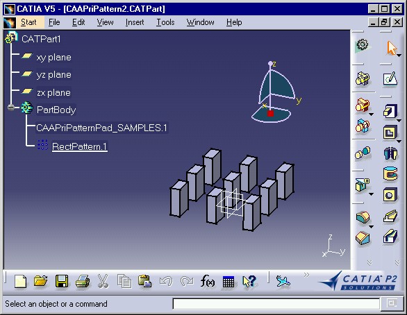
method, saves the resulting Part document, and then patterns it using a 3x3
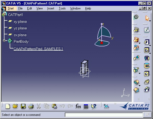
grid, and saves the result in a second Part document. Fig.1
shows the pad to pattern saved in the first Part document. Fig.2
shows the patterned pad saved in the second Part document.
 |
 |
[Top]
To launch CAAPriPattern, you will need to set up the build time environment, then compile CAAPriPattern along with its prerequisites, set up the run time environment, and then execute the use case [3].
Do not type the module name on the command line, but type:
CAAPriPatternMain e:\Parts\CAAPriPattern1.CATPart e:\Parts\CAAPriPattern2.CATPart
where:
e:\Parts\CAAPriPattern1.CATPart stores the pad to patterne:\Parts\CAAPriPattern2.CATPart stores the patterned pad.[Top]
The CAAPriPattern use case is made of two modules named CAAPriPattern.m and CAAPriPatternMain.m of the CAAPartInterfaces.edu framework:
| Windows | InstallRootDirectory\CAAPartInterfaces.edu\CAAPriPattern.m\ |
| Unix | InstallRootDirectory/CAAPartInterfaces.edu/CAAPriPattern.m/ |
where InstallRootDirectory is the directory where the CAA CD-ROM
is installed.
[Top]
There are five logical steps in CAAPriPattern:
We will now comment each of these steps by looking at the code.
[Top]
class CAAPriEManageFeatBuild : public CATPrtManageFeatBuildExt
{
  CATDeclareClass;
};
|
An adapter is provided to implement CATIPrtManageFeatBuild. To use it, you need to create a class that inherits from the CATPrtManageFeatBuildExt adapter. This class is named CAAPriEManageFeatBuild.
#include"CAAPriEManageFeatBuild.h"
// To declare that the class
// is a CodeExtension of (late type) PatternPad
CATImplementClass(CAAPriEManageFeatBuild,
                  CodeExtension,
                  CATBaseUnknown,
                  PatternPad);

#include "TIE_CATIPrtManageFeatBuild.h" // needed to tie the implementation to its interface
TIE_CATIPrtManageFeatBuild(CAAPriEManageFeatBuild);
|
CAAPriEManageFeatBuild is a code extension of the feature PatternPad to pattern. No method of CATIPrtManageFeatBuild should be redefined.
[Top]
int CAAPriEBuildShapeToPattern::BuildShape()
{
  ...
  CATIPrtManageFeatBuild_var spManageBuild = this;
  int pattern = !(spManageBuild->ReportNecessity()); // pattern = 1 for pattern context.
  ...
|
The BuildShape method is implemented by the CAAPriEBuildShapeToPattern
class and includes variants depending on the context. The context mode is
accessible from CATIPrtManageFeatBuild interface and stored in the
variable pattern. This takes place just after retrieving the CATGeoFactory
pointer.
pattern = 1BuildShape method context is Pattern.
[Top]
  ...
  if (!pattern)
    CATIGeometricalElement_var(this)->DeleteScope();
  ...
|
In pattern context, the scope deletion of the feature must not be performed. This takes place just after creating the procedural report.
  ...
  if (pattern)
    spManageBuild->SetOperand(ListSpec, ListKey);
  ...
|
The specifications used as operands to create the procedural report will be
used to perform the shape of the pattern. It is necessary to store this
information using the SetOperand method of CATIPrtManageFeatBuild.
This takes place just after creating the topological journal.
[Top]
This step takes place just before creating the prism using the ::CATCreateTopPrism
global function.
  ...
  CATBody_var spTransformBody = spProfileBody;
  if (pattern)
  {
    // Retrieves the mathematical transformation computed by the pattern
    CATMathTransformation transfo = spManageBuild->GetLocalSketchTransfo();
    ...
|
In pattern context, the mathematical transformation computed by the pattern
is retrieved thanks to GetLocalSketchTransfo method of CATIPrtManageFeatBuild.
    ...
    // Transformation of the geometry of the profile:

    // Creates a transformation operator and sets its attributes

    // The inputs of the topological operator
    CATSoftwareConfiguration* pSoftConfig = new CATSoftwareConfiguration();
    CATTopData topData(pSoftConfig, pCurrentJournal);

    CATDynTransformation *pTransformation = CATCreateDynTransformation(spGeoFactoryOnSolidCont,
                                                                       &topData,
                                                                       spProfileBody);

    pTransformation->SetReportMode(CATDynTransformation::CATDynModification);
    pTransformation->SetTransformation(transfo);
    // Performs the transformation
    pTransformation->Run();
    // Retrieves the resulting geometry
    spTransformBody = pTransformation->GetResult();

    delete pTransformation;
    pTransformation = NULL;
...
|
A CATDynTransformation is created with the appropriate parameters, that is, the factory, the body to transform, and the topological journal. At this step, the body to transform is the sketch. This CATDynTransformation instance is defined as a modification, and is assigned the retrieved mathematical transformation. Then it is run to apply it to the result geometries from sketches and other geometrical elements which influence the shape form. Then, its result is retrieved. This result is the patterned sketch of PatternPad.
    ...
    // Transformation of the pad direction

    CATAngle angle(0.);
    CATMathLine axis;
    CATBoolean isRotated = transfo.IsRotation(angle, axis);
    if (isRotated)
    {
      direction = transfo * direction;
    }
  }
  ...
|
If the mathematical transformation is a rotation, get its axis and angle, and apply it to the PatternPad direction.
Then, the BuildShape method resumes to create the prisms using
the transformed spTransformBody and direction using
the ::CATTopCreatePrism global function.
[Top]
This takes place just after having created the prism.
  ...
  if (!pattern )
  {
    // Stores the procedural report
    spReport->StoreProcReport(spSolid, NoCopy);
  }
  ...
|
In the pattern context, the procedural report is not stored.
  ...
  else
  {
    // Sets the geometry performed
    spManageBuild->SetBody(spSolid);
    // Sets the topological journal
    spManageBuild->SetCurrentJournal(pCurrentJournal);
  }
  ...
|
However, the computed shape and topological journal must be stored because they are necessary to compute the shape pattern.
[Top]
This use case has demonstrated the way to manage the BuildShape
of the patterned feature.
[Top]
| [1] | Form Feature and Contextual Feature Concepts |
| [2] | Implementing a Mechanical Design Feature Building |
| [3] | Building and Launching a CAA V5 Use Case |
| [Top] | |
| Version: 1 [Jan 2000] | Document created |
| [Top] | |
Copyright © 2000, Dassault Systèmes. All rights reserved.