
Analysis Solution |
Analysis Modeler |
Local AxesThe definition of local axes in the Field Model |
| Quick Reference | ||
AbstractThis article explains the kind of local axes provided with the analysis modeler. These axes are used for the preprocessing in order to define vectors, tensors in a specific coordinate axis system. |
The local axis are manipulated with the CATAnalysisExplicitAxis class. This class is build by derivation of CATAnalysisExplicitEntity and have some dedicated methods to convert coordinates system. The associated category of the entity is "AXIS". Three kind of axis definition exist as described after. For each kind, the three points defining the axis can be expressed as coordinates or as existing nodes. An axis is considered as valid if the three points of the definition allow to build a 3D axis, this means points have to be non collinear and non coincident.
The physical types that define the points for an axis based on coordinates are:
A local axis that is defined with coordinates can be defined in another axis system. In this case, the physical type LOCAL_AXIS defines the local axis in which the coordinates are expressed
The physical types that define the points for an axis based on coordinates are:
Notes:
[Top]
Two physical types of axes can be used:
|
AXIS_RECTANGULAR_3D_NODE
|
AXIS_RECTANGULAR_3D_COORDINATE
|
For example the point P is is defined by it's coordinates (X, Y, Z) in such a local axis.
[Top]
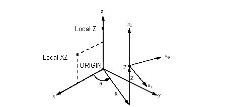
Two physical types of axes can be used:
|
AXIS_CYLINDRICAL_3D_NODE
|
AXIS_CYLINDRICAL_3D_COORDINATE
|
For example the point P is is defined by it's coordinates (R, ![]() ,
Z) in such a local axis (defined without reverse).
,
Z) in such a local axis (defined without reverse).
[Top]
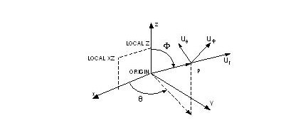
Two physical types of axes can be used:
|
AXIS_SPHERICAL_3D_NODE
|
AXIS_SPHERICAL_3D_COORDINATE
|
For example the point P is is defined by it's coordinates (R, ![]() ,
,
![]() ) in such a local
axis (defined without reverse).
) in such a local
axis (defined without reverse).
[Top]
To create an axis, to kinds of scenario can be described:
You create a feature that is build by derivation of "AnalysisAxis". In this case you can implement on the feature the CATISamExplicitation Interface that will create an CATAnalysisExplicitAxis inside the field model.
You create a feature that defines some characteristics base on implicit axis defined on a geometry (Cylinder...), in this case you can build in the Field model an entity in which the characteristics will be expressed in a global axis system or in a local axis system.
For the second case, in the implementation of CATISamExplicitation of your entity that we will call EntityXXX in the next lines:
A standard sample of CATISamExplicitation can be found in the references.
| [1] | Analysis Modeler Overview |
| [2] | Sample for CATISamExplicitation |
| [3] | Manupulating explicit pointers |
| [Top] | |
[Top]
| Version: 1 [Jan 2003] | Document created |
| [Top] | |
Copyright © 2000, Dassault Systèmes. All rights reserved.